Shear Testing
Shear Cell
The FT4 Powder Rheometer® also includes a Shear Cell accessory which allows the powder’s shear properties to be quantified. The technique has been published by the ASTM International Committee D18 on Soil and Rock. Shear testing is a very different technique to that of dynamic testing, and always characterises the powder in a consolidated state. It is also a fairly static test, measuring powder behaviour as it transitions from no-flow to flow.
For these reasons, it is clear to see why shear cells are ideally suited to predicting powder behaviour in process operations where the powder is consolidated and where flow rates are low and / or sporadic. They have been successfully applied for understanding powder behaviour in hoppers, and also provide some of the data needed to carry out a hopper design exercise (based on Jenike stress theory developed during the last century). However, as a consequence of the regime in which they operate, they are less suited to predicting powder behaviour in low stress or dynamic applications, such as mixing, filling, feeding and conveying.
Operating Principle
At very low speeds, a shear (or horizontal) force is applied to an upper layer of powder whilst the adjacent lower layer is prevented from moving (or vice versa). The force continues to increase but no relative movement at the shear plane occurs until the shear force is sufficiently high to overcome the powder’s shear strength, at which point the powder bed ‘yields’ and the upper layer of powder slips against the lower.
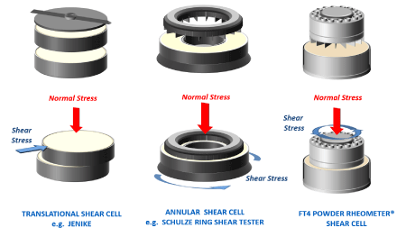
Several types of shear cell design have emerged over the last 50 years, however each employs the same concept of shearing one layer of powder against the other. The designs most frequently in use today are rotational in nature, and are preferred as they allow the two layers of power to be sheared relative to one another over a large distance, in contrast to translational designs that quickly exhaust their range of displacement.
Each design has its strengths and weaknesses, and all types remain in use today. For a detailed comparison of features, benefits and weaknesses, please contact us directly for further information.
In a typical shear cell test sequence, several shear tests would be carried out at different levels of normal stress. The data produced represents the relationship between shear stress and normal stress, which can be plotted to define the powder’s Yield Locus. In simple terms, the higher the shear stress for a given normal stress, the less likely it is that the powder will yield and begin to flow when confined under a similar consolidation stress in a hopper or other vessel.
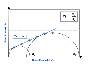
It is possible to apply a number of mathematical models to this data, but it is important to consider that in doing so, trends may be exaggerated or reduced. Fitting Mohr stress circles to the yield locus identifies the Major Principle Stress (Sigma 1) and Unconfined Yield Strength (Sigma c), and the ratio of the former to the latter quantifies the Flow Function, FF. Flow Function is a parameter commonly used to rank flowability, with values below 4 denoting poor flow and above 10, good flow.
Wall Friction
The Wall Friction test provides a measurement of the sliding resistance between the powder and the surface of the process equipment. This is particularly important for understanding discharge behaviour from hoppers, continuity of flow in transfer chutes and tablet ejection forces. It is also useful when investigating whether a powder will adhere to the wall of process equipment and various other surfaces, such as the inside of sachets, capsules and other packaging material.
The measurement principle is very similar to the shear cell test, but rather than shearing powder against powder, in this test a coupon of material representing the process equipment wall is sheared against the powder in question. The FT4 Wall Friction accessory allows for a range of coupons to be investigated, and bespoke surfaces can be manufactured if required.
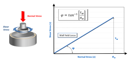
Data is typically represented as a plot of shear stress against normal stress, allowing the determination of Wall Friction Angle (phi). The greater the wall friction angle, the higher the resistance between the powder and wall coupon.
This data can be utilised in specific studies, as outlined above, but is also required as part of a hopper design exercise.
Hopper Design
Hoppers are used extensively throughout the processing environment and whilst they are often considered to be simple systems, they are responsible for causing a great deal of process interruption and product quality issues.
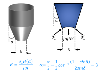
If a powder possesses properties that are not optimised for the hopper geometry and equipment surface, then flow from the hopper may be variable or even none existent. However, since the pioneering work carried out by Andrew Jenike in the mid twentieth century, it has been possible to utilise data from shear cell and wall friction tests to calculate the critical hopper dimensions to ensure good flow.
The FT4 comes with fully automated hopper design software, which takes the results directly from shear cell and wall friction tests and runs the data through the hopper design algorithms. The result is a fully automated hopper design exercise in less than 3 hours.
Today, this hopper design process remains one of the very few fundamental approaches to equipment design, based on an understanding of material properties and the stress regime within the equipment. Unfortunately, such an approach is not available for mixers, feeders, conveyers, dryers, compression processes or any of the other unit operations routinely used in powder processing.